The electrical resistivity method is one of the oldest geophysical methods, originally designed in the 1920s for mineralogical prospecting by the Schlumberger Company in France. Since then, electrical resistivity methods have been used to find potable groundwater supplies, trace contamination as it migrates through the saturated zone, determine soil resistivity for purposes of designing electrical substations, grounding arrays, and estimating pipeline corrosion. Electrical resistivity is used to detect shallow structures and subtle changes in soil apparent resistivity, which also makes it conducive for using it in archaeology surveys.
The resistivity method typically uses a four-electrode array, two current, and two potential (voltage) electrodes, in specific geometric configurations called arrays, for data acquisition. A very low-frequency or direct current is applied to one of the current electrodes, and the current flows through the earth to the second current electrode, closing the circuit. The potential difference, or voltage, between the two potential electrodes is measured by the instrument, and Resistance determined using a very simplified version of Ohms Law: V=IR ; V is voltage, I is current in amps and R is resistance in Ohms.
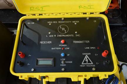
RSI uses a L and R Super Mini Res Resistivity Meter developed by Mr. John Fett and Mr. Byron Arnason of L and R Instruments. Resistance is then automatically calculated by the resistivity meter, and displayed on the LCD display, where it is recorded on a PDF data logger. The parameter that is actually contoured and from which an interpretation is derived is called apparent resistivity. This is because Resistance values, besides being influenced by a soil's mineralogy, porosity, and water saturation, is also influenced by the electrode geometry used. By converting Resistance values to apparent resistivity values, the influence of the array configuration is removed from the data. Apparent resistivity is calculated by the equation: p app=2nR(GF) where p app is apparent resistivity in Ohm-meters, R is resistance, and GF is the geometric factor intrinsic to the current and potential electrodes configuration.
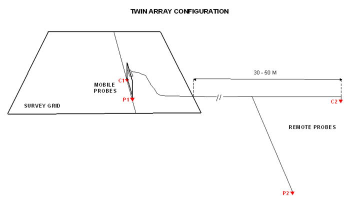
In engineering and environmental geophysics surveys, a Wenner Array is typically used, where the geometric factor is "a" or the A-spacing (i.e. the distance separation between any two electrodes). However, for archaeological surveys, a twin probe array configuration is recommended for its superior delineation of near-surface features, ease of use, and rapid deployment and data acquisition. With the Twin Array configuration, one current (C1) and one potential (P1), electrode pair, separated by a short, fixed distance, is moved from station to station along resistivity survey lines. The maximum spatial resolution is equivalent to the mobile electrodes separation distance, typically 1 meter for archaeology surveys. The approximate investigative depth is approximately 1 to 2 times the C1-P1 separation. For the Twin Probe Array, the other current (C2) and potential (P2) electrode pair are located at a remote distance away, at least 30 meters from the mobile electrode pair. Below is a schematic of the Twin Probe Array configuration.
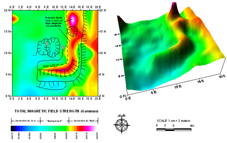
Calculated apparent resistivity values can be displayed as 1D profiles and modeled to determine soil lithology and depth to bedrock at any one station location. They can also be contoured and presented as 2D and 3D images, such as the one below obtained after one of RSI's surveys for the National Park Service (bottom left). Dipole-Dipole data, or data acquired in Multi-channeled arrays can be displayed as pseudo sections, where electrical resistivity is plotted as a function of depth and horizontal distance (bottom right).