
The ground penetrating radar (GPR) methodology is a very high frequency EM technique used to produce high-resolution images from the subsurface. GPR is used for both target detection (i.e. detecting abandoned USTs, utilities, drums, burials, archaeological artifacts, etc.) and for characterizing the subsurface stratigraphy, water-table, or geology in hydrogeological, environmental, and geotechnical site characterizations. When used at the same site, but surveyed over time, GPR is also an effective methodology for monitoring contamination migration from the surface.
The GPR method operates by transmitting low-powered microwave energy into the ground using an ultra-wide band (UWB) transceiver antenna. EM energy from the antenna propagates at frequencies ranging from 10 MHz to 3 GHZ, although antenna frequencies for commercially available antennas typically range from 200 MHz to 1.5 Ghz. The peak power of this antenna is 20 to 100 times less the wattage of a cellular phone, and the energy is directed into the ground (and not at the operator) by means of shielding on the top side of the antenna. The GPR signal is then reflected back to the antenna by materials with contrasting electrical impedance, which is primarily determined by dielectric and conductivity properties of the material, its magnetic permeability, and its physical properties. The greater the contrast in the real dielectric permittivity (RDP) of two materials, the greater the reflection amplitude. Typically, high-amplitude reflections occur at lithological or mineralogical changes, or where there is a sudden change in water content.
A material's dielectric properties are primarily determined by mineralogy, and water content. A soil with a high iron and/or magnesium content, or one that contains mineralogical clay or other platy minerals, will have a higher RDP value than a quartz-rich sand. Similarly, a soil that has a high porosity and is water saturated will have a higher RDP for the same unsaturated soil. The RDP of a pure DNAPL such as perchloroethylene (PCE) is low, approximately 2.4 (Sneddon et. al., 2000, and Sander et. al., 1996), and therefore would produce a large dielectric contrast when it displaces water within a water-saturated soil.
Reflections observed on GPR records can be non-unique, meaning that a similar reflector can be caused by different objects. Strong reflections are typically produced from metal objects, which has an RDP of 1,000, the water-table, and clay layers. The schematic below shows the different ways reflections can occur. Objects, such as utilities, that have a discrete length and width typically produce hyperbolic reflections on GPR records.
RDP values of soils have been determined from laboratory measurements (Kutrubes, 1986, Olhoeft, 1987, and Canan, 1999), and measured in-situ and calibrated based on measuring a target at known depth (such as a culvert) or from borehole logs. GPR propagates well in unsaturated or minimally saturated sands and gravels, which have a relatively low RDP value, approximately 6 to 7. It is not uncommon that an unsaturated gravelly soil would have a velocity of about 0.35 foot per nanosecond (ft./ns). Therefore, the dielectric contrast between the water table and the unsaturated overburden, should be sufficient to produce a reflection on the radargram using the GPR methodology. Ideally, GPR could also be used to trace contaminants as they migrate through the soil over time, provided that there is sufficient dielectric contrast between the contaminant and the soil. For instance, the RDP contrast between a water saturated sand and gravel soil, with an estimated RDP of 12 to 15, and a DNAPL, with an estimated RDP of 2.4, should produce a good reflection on the GPR record.
In the absence of water, physical changes in densities, or a relatively large or irregularly-shaped inclusion in the soil, can cause weak radar reflections. For instance, boulders are detectable within the surrounding soil, not only because of subtle lithological contrasts, but because their irregular shape causes reflection and diffraction of the GPR waves.
The success of the GPR methodology also depends on the amount of EM signal attenuation experienced at any given site. GPR signal attenuation is caused by four loss mechanisms: conductive losses, molecular relaxation losses, "clay" (or interfacial polization) losses, and scattering losses (Kutrubes, 1986). By far, the greatest source of loss is caused by conduction losses, which are most severe at frequencies of 300 MHz and below. The greater the soil/medium conductivity the more attenuation and loss of resolution there will be. Road salt contributes to conduction signal loss, even in the warm months and after heavy rains, as road salt still resides within the asphalt pores and soils beneath it.
Molecular relaxation losses occur when polar molecules rotate and oscillate in response to the applied EM field. Applied energy is converted to kinetic energy used to energize and rotate the molecule. Kinetic energy is then converted to thermal energy, because of the frictional drag created by molecular rotation. Neither kinetic nor thermal energy is detectable to the GPR system, so as the applied EM energy is converted, it is lost. The higher the frequency of the applied EM field, the faster these polar molecules rotate in response to that applied field. Eventually, as the frequencies increase, the polar molecules cannot rotate fast enough in response to the applied field, and so at that frequency, called the relaxation frequency, molecules become stationary again, and polar molecules are no longer a source of EM signal loss. The best known polar molecule is water, H2O, which undergoes molecular relaxation at 10 gigahertz (10 x 1E9 Hz). However, "water losses" start to become significant at frequencies of 600 MHz and higher.
The third type of loss is attributed to clay or other colloidal type particles. Mineralogically, clay is unique, as it consists of elongated ("colloidal") platy particles which have an uneven distribution of charge across them. Negative charge accumulates on the exterior of the clay, while positive charge tends to accumulate within the platy crystal lattice structure. As an EM field is applied, the charge on the clay particle migrates in response to the applied field, causing an electrical "double layer" where there are negative ions on one side of the colloid, and positive charge on the other. As charge migrate across the clay particle, kinetic energy is converted to thermal energy, and again, rendered lost to the GPR system. Experiments conducted by Olhoeft (1986a) have shown that even a small percentage of clay will attenuate the GPR signal, especially when wet, resulting in reduced signal penetration and resolution. While there was no clay observed at ground surface or within the boring logs, it is possible that a thin till deposit may be present at depth. Once encountered, there would be limited GPR signal penetration below the clay-rich layer.
The fourth type of loss, "scattering losses: are caused by irregularly-shaped targets causing an unpredictable redirection of GPR signal away from the receiving antenna. This type of loss becomes a factor when the wavelength of the applied EM field is 3 to 10 times smaller than the size of the target. Scattering losses are more a factor for the smaller wavelength, higher frequency 400 MHz antenna, used typically in urban areas, especially where demolition debris has been used for fill.
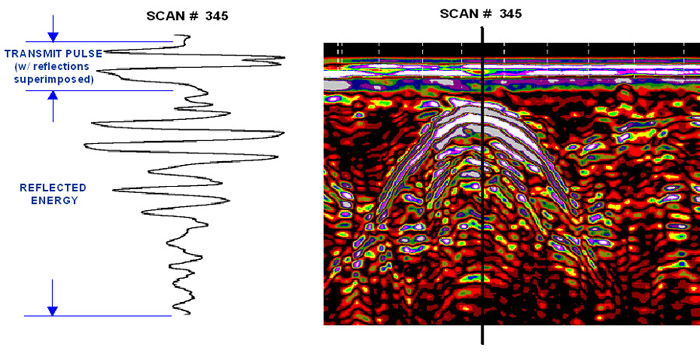
RSI owns and operates three different Geophysical Survey Systems, Inc. GPR systems and 2 Senor and Software GPS systems. The GPR system consists of three major components: the control unit, which is a proprietary computer controlling data acquisition, presentation, and storage; the antenna, which steps up low-voltage EM energy received from the controller and propagates microwave and radio frequency EM energy into the ground; and the transducer cable, which allows communication and transference of energy between the two. A mono-static antenna houses both the transmitting and receiving antennas in the same fiberglass housing. This means that the recorded waveform observed on the GPR records consist of a transmit pulse, located at the top of the radar record, and superimposed on it are reflections from the subsurface. In a relatively resistive environment, the transmit pulse width of a 400MHz antenna would be 2 ns of the total range of the signal, whereas the upper 12ns or so would represent the transmit pulse of the 60MHz antenna. This would mean that reflections of at or near-surface features would be superimposed upon the transmit pulse. The schematic below shows a single waveform, and corresponding line scan image, which is created by assigning a color to a specified amplitude range.
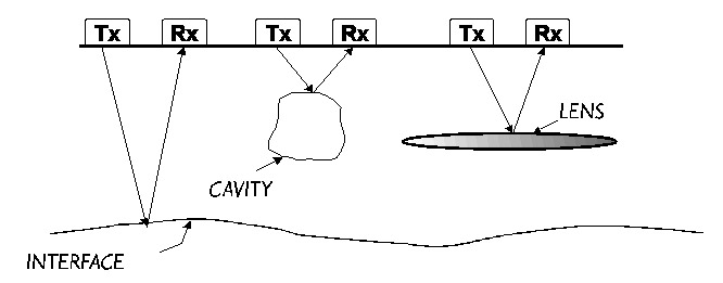
Above: Schematic showing that GPR reflections occur where there is a change in dielectric properties, such as at an interface of two materials or at an object.
Data is typically processed and imaged as 2D and 3D time-depth slices using GPR-Slice© software developed by Dr. Dean Goodman of the Geophysical Archaeometry Laboratory . This state-of-the-art 2D and 3D GPR imaging software quantifies GPR results by digitizing the amplitude of reflection from each GPR record, looks for horizontal correlation of features across adjacent and nearby parallel lines, assembles them into a 3D image, then contours the data at each time/depth interval specified by the user.
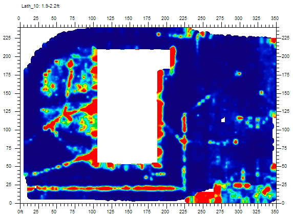
Above: Depth slice image also generated with GPR-Slice© showing linear utilities approximately 2 feet below grade.
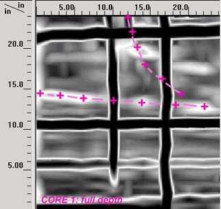
RSI also processes GPR data using RADAN©, a proprietary software package developed by GSSI, for filtering and enhancing data quality. RADAN© is also used to generate X-ray like images from structural slab surveys using STRUCTSCAN, such as the ones generated below.
GPR signal penetration is site specific, determined by the dielectric properties of the soil or man-made materials such as asphalt and concrete, the amount and spacing of metal reinforcement in concrete, and the conductivity and moisture content of the soil and fill materials. GPR signals propagate well in sand and gravel. Conductive soils such as clay, or fill saturated with brackish or otherwise conductive groundwater, cause GPR signal attenuation and loss of target resolution (i.e. limited detection of small objects).
GPR is an interpretive method, based on the subjective identification of reflectors which may not uniquely identify an object. Buried utilities, when crossed obliquely by the antenna, have a similar hyperbolic signature as other metal objects such as drums and metal scraps. Cobbles, bricks, and cinders can also appear as hyperbolic reflectors on the radar record. Obtaining data along multiple survey traverses helps determine the size, shape, and continuity of buried objects. For instance, buried utilities may be interpreted from hyperbolic reflectors which are aligned along adjacent lines. Because of the subjections of GPR data interpretation, confirmation using boreholes or test pits is strongly recommended.
The antenna radiation pattern is cone-shaped, emanating GPR signals approximately 15 degrees from horizontal fore and aft of the antenna. Therefore, buried objects may be detected before the antenna is located directly over them and GPR anomalies may appear larger than actual target dimensions. When station locations are recorded manually instead of using a distance-calibrated survey wheel, changes in the speed at which the antenna is moved between stations causes slight errors in horizontal distance scaling. Hence the interpreted horizontal position of an object may have a small error. Such interpolation errors can be minimized by using station spacing's appropriate to the anticipated target dimensions.